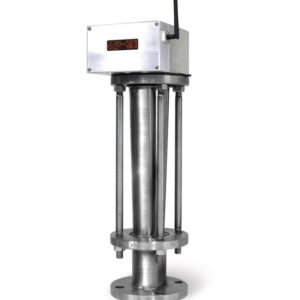
Description
The flow inside of the venturi meter is accelerated by the 21±1º angle converging cone and the flow will be measured using the differential pressure between upstream of the cone and throat. Venturi tube with machined convergent of angle of 10.5±1º may be used in accordance with ISO/TR 15377. The fluid slows down in a cone with smaller angle(7-15º) where most of the kinetic energy is converted back to pressure energy. Because of the cone and the gradual reduction in the area there is no “Vena Contracta.” The flow area is at a minimum at the throat.
Though 0.995 and 0.985 of the coefficient of discharge(Cd) are designated for machined type and welded type respectively as a standard, they can be changed significantly at the low Reynolds number. See ISO 5167-4:2003(E) Annex B.
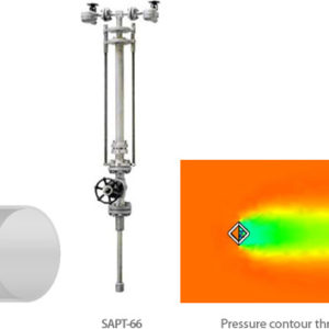
The pressure recovery is much better for the venturi meter than for the orifice plate.
Standard Specifications
| Connection | ISO 5167 (1991 & 2003 Edition) |
|---|---|
| ASME MFC-3M | |
| Flanged & Welded | |
| β-Ratio | 0.4 to 0.75 for machined (ISO 5167) |
| 0.4 to 0.70 for welded (ISO 5167) | |
| 0.3 to 0.75 for machined (ASME MFC-3M) | |
| 0.3 to 0.75 for welded (ASME MFC-3M) | |
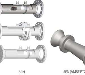
| Venturi type | Machined type |
| Welded type | |
| Tetragon duct type | |
| Tapless |
| Tappings | 1/2″ NPT |
|---|---|
| Others are available on request | |
| Rangeability | ±1 % to ±2%(uncalibrated) |
| 5 : 1 for indication or recording | |
| 3.5 : 1 for control application |
Options
- Nipple
- Tap valve
- Piezometer rings or Annular chambers : this is mandatory by ISO 5167, but we will apply for the above as an options on request only.
- Straightener (per ISO 5167, API 14.3 (AGA 3 part 2)
- Others are available on request
- Full jacket or Semi jacket for heating or cooling(SVT-J)